Saturday, May 6, 2023

A2VGA - Pico IIe Card


The A2VGA - Pico IIe is an Apple IIe specific VGA card for the budget conscious user. This card like many of the Apple II RGB video cards uses the raw video signals from the Apple IIe auxiliary slot. It's constructed from easy to obtain, through hole and relatively inexpensive components. These include the Pi Pico microcontroller, a level shifter, a diode, several resistors, sockets and some optional buttons. This is a product of my previous video investigations. Since I've had bugger all hobby time in quite a while I’ve only managed to get this knocked out because it’s been a small task. I guess you can say this is picking the low hanging fruit from the possible video cards I could have tackled.

Since the card uses the same signals which are available on the Apple IIc video port, The A2VGA - Pico IIc will be available at a later stage. This will contain the same firmware but will have a different form factor plus a 12V to 5V step down converter.

The card is super simple to build, super simple to use and super simple to update the firmware on. No special tools are needed for updating the firmware. Connect a USB cable from your PC to the Pi Pico and when a new drive pops up, you just copy to it the latest/desired firmware. Done. That's it.

The card can be used by itself if the Apple II only needs to run with 64kB. Extra memory needs to be plugged into the piggyback slot to run more memory hungry software and to use the DHGR video mode. The AIIE 80COL/64K MEMORY EXPANSION card works well as extra memory however, taller memory cards may have issues fitting under the lid. Once the memory card is inserted into the piggyback slot it is difficult to remove. I use a small screwdriver to gently lever the memory card out using the provided PCB holes.

I tested the card's display lag (see a previous post of mine if you are interested in how this is achieved) and on the Samsung SyncMaster 740N monitor I found that it was one frame behind the CRT monitor while on the DELL U2410 monitor it was two frames. I believe most of this delay comes from the monitor itself since the A2VGA does not have a video frame buffer as such. An internal A2 monochrome buffer is updated after every 32 bits that are read from the A2 bitstream. Independently the VGA generation part just processes and spits out a line at a time and performs this as fast as it can.

The card works by using the following video signals:

The required signals:
- 14M : Apple II video clock.
- SEROUT* : Luma part of the video signal ie the monochrome pixel bitstream.
- WNDW* : Start of line being displayed or SYNC* - Start of line at the left border. I provided a logic analyser screen shot showing the difference between WNDW and SYNC in my last video post.

Optional signals that are nice to have.
- GR : Sets up each line to display in colour or monochrome.
- LDPS : Not implemented on this project. Each Apple II display line is 560 pixels long (it does not matter what video mode is being used by the Apple II) however the starting location on the screen changes based on the video mode. For example, the 80 column text mode starts at a different location on the screen compared to 40 column text mode (four pixels of difference). LDPS can be used to align these video modes. Using a typical monitor, you get a black border around the displayed picture so most people will never notice this effect. I used this signal in my video streamer project because the display was in a 560 pixel window, meaning that without this signal I would have resorted to either chopping off one of the modes by 4 pixels or adding an unwanted vertical bar to the left or right side of the picture depending on which mode was selected.

How it works:
The input PIO section of the Pi Pico records the accessory bits (GR, LDPS if needed) and then 560 screen pixels into a 32bit aligned structure for each line. The monochrome A2 buffer needed is just over 14kB. This is a fraction of the 256k Pi Pico RAM available. The VGA generation code runs independently. Each VGA line is pre calculated based on a specific A2 colour model (AppleWin’s Composite Idealized) before being sent to the output PIO section. This section drives the VGA resistor DACs (Digital to Analog Converters) and Sync signals. The A2 display area 560x192 is displayed within the standard 640x480 resolution. The lines are doubled to produce a squarish look. When in scanline mode, every second line is blacked out making this appear as if the monitor contains scanlines. The colour model is a two-stage transformation. First, using a twelve-bit scrolling window, where the middle four bits are translated into four coloured pixels (each coloured pixel being 4bits ie the 16 Apple II colours). Then the second transformation converts each of these coloured pixels into the closest matched Apple II display colour using 16 bits (RGB565).

I’ve implemented the best looking colour model that I have at the moment. I’ve also turned on the scanline effect. I have not used any of the buttons yet. The board can output RGB565 however I got the project working using RGB555 since that was what the example project was configured for. I’m sure it is not going to make much difference, so I 'm not in a rush to fix it. I’ve still to test several options like the resistor values used for the DACs. I’ve used precise resistors ie 500k, 1k 2k, 4k, 8k and 16k however, resistors do not normally come in these values. They are obtainable but I would like to see how much of a difference it would make to the display if standard resistor values were used instead.

I’m looking at making some changes to the next PCB revision. These changes include:
1. Add an option for the VGA socket to be PCB mounted or externally connected via a cable.
2. Fix ribbon cable pinouts. Currently they are very close together making it horrible to wire on the cable.
3. Use 74LVC245 instead of the 4 line MOSFET level shifter. This will allow more signals to be added. I want to add Sync in case someone wants to rewrite my firmware using a different method. If you have any other signals you wish to add (which are available on both the Apple IIe aux slot and the Apple IIc video port) then let me know. I'll consider adding them as well.

Concerns
1. The NTSC Apple IIe aux port is in a different location to a PAL aux port. I don't have a NTSC IIe motherboard to test on. I’m estimating clearances by going of pictures of motherboards.
2. Electrical interference. VGA is analog so you may experience noise from electrical interference, especially if a ribbon cable is going to be used for routing the VGA plug to the rear of the case. I can see slight interference effects on the display when looking for them. This is on one of my monitors while the other monitor looks totally fine. I get a different effect when using the IIe vs using the IIc. For example, I tried to locate a small shimmer that I am seeing when using the Apple IIc. I have tracked this down to being caused by the IIc power supply on the ground line. Not sure what I can do to mitigate this. More testing is needed.

The VGA generation pretty much uses an entire core and one of the PIO modules. The Raspberry Pi SDK VGA generation code could be replaced by an alternative, much simpler model (there are a few of these around) if more processing power is required. The second PIO is partially used up with importing the A2 video stream. Currently, the second core is only being used by one interrupt which occurs at the end of each line (handles the A2 horizontal and vertical sync processing).

The Pi Pico runs much slower than then Raspberry Pi Zero so I found that the colour model needed more optimisation to make it work. I'm happy that I was able to get it running without having to overclock the processor. To obtain better colour models (where higher screen resolutions are required and larger colour ranges ie RGB888) I suspect something more powerful than Pi Pico is needed. If efficiency was of no concern and money no object then we could throw a 3GHz processor at the problem and have something running that looked like OpenEmulator. However, I believe that there is a middle ground where FPGAs or Pi Zero like devices could be used to generate great colour models.


I've been tesing on the IIc for the most part because it is much easier to access the card.

Project files will be provided once the final card design is worked out, a schematic generated and the code cleaned up.

Here is a video of the cards output. https://docs.google.com/open?id=1ZbibOvvSFw8lRugwCkTYdhJfkaTdboKr


Update: 6th June, 2023.


Display of 80 Column Text. Note: scan line emulation is turned on.


Colour Killer testing, Mixed Mode (monochrome and colour) testing - VIDD7 mask, Power regulator testing.

Wednesday, May 3, 2023

Apple IIGS to RGB Adapter


On my hobby desk I usually keep my 9inch Sony monitor sitting around as it does not take up a lot of room. It supports composite as well as RGB so I can quickly connect up any of my Apple II variants. For the IIGS I've been using a bogey custom cable that I knocked up a long time ago. It's always been a pain for the times when I need the cable to be just a fraction longer. So it's been on my to do list for a while to put together an adapter so that I can use any of my various length component RGB cables. I recently put in to get a bunch of PCB boards made up and took the opportunity to include a PCB for a IIGS video to RGB adapter. I've allowed for a spot to attach an extra RCA socket in case I ever have a monitor which requires an external Sync signal.


Friday, March 24, 2023

Native Two Joystick Gameport Support


Did you know that the Apple II computer contains native multiplayer non-keyboard support? Over the years I've documented this functionality being done with digital joysticks but since I've also been involved with native two joystick game enhancement projects, I figured it was a good time to document these as well.

All Apple II models contain a 16 pin or a 9 pin plug providing support for a single joystick. This means all you need is a paddle set like the following to play multiplayer paddle games such as Warlord or Star Thief. The first paddle uses the x-axis part of the joystick and the second paddle uses the y-axis part.


Multiplayer joystick games such as One-on-One, Archon I & II, DogFight and Superstar Ice Hockey (IIGS only) can also be played natively on the Apple II however an adapter is required to make this happen. This is because the Apple II only contains a single physical game port (16 pin or 9 pin). This needs the second joystick signals routed to a new second joystick port. Commercial adapters such as the Wico joystick adapter or Paddle-Adapple perform this function but I've seen modern incarnations of this adapter being sold. Alternately, you could build one of these yourself since the connections are very simple. Probably one of the simplest enhancement projects you could make for the Apple II. This will work on all Apple II models except the IIc / IIc+. On these models the second joystick signals were replaced with digital mouse signals.


The wiring convention was to have only one trigger button per joystick (PB0 for Joystick 1 and PB1 for Joystick 2). For my converter, I've added a switch allowing me to swap between single player (PB0 and PB1 maps to joystick 1) and dual player (PB0 and PB2 maps Joystick 1, PB1 and PB2 maps to Joystick 2). The extra button, PB2, allows for a common function say, starting or pausing a game.

Just recently Michael contacted me and asked for assistance with the conversion of the game Mario Bros to dual analog joystick support. I thought this was a great idea and because I've already done a few patches to this game, it did not take long to perform the conversion. I'm weary of the fact that dual analog joystick code, in computing terms, can take a long time to process. I suspect this is the reason why not many games support this functionality. However, Mario Bros only requires one axis (left/right movement) per player so this should not be any more taxing on computing resources than any other Apple II joystick-based game. It plays very well and is a lot of fun in co-op mode.

The other project that I was lucky to have been involved with (helping with testing) was Nick's conversion of the game Robotron: 2084. The original game is single payer but uses two joysticks, one for movement and one for shooting. The story is that its creator, Eugene Jarvis who also created Defender, had a broken arm at the time so couldn't use buttons. Nick couldn't understand why the author for the Apple II version hadn't added this mode into the game. So he tracked him down and quizzed him on various parts of the code. Nick disassembled the game, added the mod and added the author's name (Steve Hays) to the credits. He really deserved that. What I love more than playing this game on the Apple II is playing this game in AppleWin and using two thumbsticks on the Logitech controller. Nick said that adding the thumbstick support to AppleWin was a bit or work, but worth it for arguably the greatest classic shootem-up. I tend to agree. It's a fast paced game with lots of things going on at once. You're always just a fraction away from being annihilated. That is how it is meant to be played. It's on the edge of your seat type stuff and a spectical to watch when played well.

Here is the stand I setup at the 2017 OzKFest gathering for showing off the conversion.


Attached is a zip file containing the converted games, conversion documentation and schematics for the joystick adapter (both Michael's version and mine).https://docs.google.com/open?id=1xwcqHOAhXEmHleHvQRsnNdBCJY9tKehv
Here is also a link to Michael's You Tube video presentation where he discusses the joystick adapter. https://youtu.be/N24VPiIjzCA

Happy gaming.


Update: 10th October, 2023.


For the soldering session at OzKFest 2023 I created this simple board.

Saturday, February 26, 2022

Apple II video to HDMI using a Raspberry Pi Zero / Pico


Example output from an Apple II video to HDMI adapter that I have been toying with. Pictured is one of the many colour models. The dual colour mode represents how the Apple II's video is inherently monochrome and yet the use of artifact colour results in a decent colour depth for such a small storage footprint.

In September 2021, Rob, a fellow Apple II enthusiast posted some images of an RGBtoHDMI, a Raspberry Pi based HDMI video solution, being setup on his Apple II. It sparked my interest because back in 2015 I looked into using the Raspberry Pi as a HDMI video display solution. This was around the time I was working on the "A2 Video Streamer" project. I couldn't see how the Raspberry Pi could capture signals consistently and fast enough to process the A2 video stream so I implemented a solution using the BeagleBone Black instead. Even though my devices worked, neither of them were user friendly enough to warrant further development. I don't see these projects as failures but as learning opportunities and stepping stones to bigger and better solutions. The RGBtoHDMI has given me new ideas to investigate.

The RGBtoHDMI is an amazing project. (https://github.com/hoglet67/RGBtoHDMI/wiki) It began as a HDMI interface for the BBC Micro but because of its flexibility it has been modified to support many computer systems of the same era, including the Apple II and the Apple IIGS. It's made up of two main parts. One being the CPLD which handles the level shifting, digital or analog signal sampling and the bit shifting while the Raspberry Pi Zero handles the pixel clock and frame image generation. It generates the right frequencies that allow it to synchronise to a computer's video clock. However, this comes at a price. It pretty much maxes out the RPi Zero's CPU. Even though it can output Apple II video to HDMI, using this device for the Apple II, in my opinion, is not overly efficient (I'm talking about the TTL signals here and not the composite one). The Apple II provides its own pixel clock so the majority of RGBtoHDMI's awesomeness, in this situation, is not needed. Instead, I would prefer to use the RPi Zero's CPU resources to perform better video emulation. The source code for RGBtoHDMI is huge and complex. I wanted to take a more simplistic approach.


Raspberry Pi Zero being used for video output and a few of the many failed attempts at getting a stable picture.

I wanted to revisit the Raspberry Pi to see if it was capable of being a simple modern day Apple II video solution. Especially now with the tiny size of some Pi models. I started off by using the RPi Zero to sample Apple IIc video signals directly (after going through level shifting of course). To get the maximum amount of power available out of the RPi Zero, bare metal programming was used. Not true bare metal. The manufacturer's firmware is still being used to setup the communications and the video but then everything after that is bare metal. Even then, using the general GPIO interface, I wasn't able to obtain a stable picture. I tried running the program in C, in assembler (manually optimised), using DMA and even running the code on the Video Processing Unit (VPU) but with no luck. The Apple II pixel clock being just above 14MHz means that sampling needs to be performed at around the 30 mega samples per second mark. I was getting in the high 20s but the readings were not consistent. We have a situation where the Apple II is outputting the video stream at a consistent rate but the RPi Zero only wants to read the data when it feels like it. The RPi Zero is not a microcontroller. It's a computer and the GPIO is isolated from the CPU. This means that it is difficult to control high speed parallel data coming in. In most situations the RPi Zero will be the master and dictating when and how the data is being transferred. We don't have that luxury here so a new plan was needed.

Digging deeper into the RPi Zero, there is an interface which shows potential as a high speed parallel means of reading in data. That interface is the RPi's Secondary Memory Interface (SMI). There isn't a lot of documentation on the interface or example projects, especially when it comes to bare metal. However I did find enough to get me started and plenty to keep me experimenting. The worst part of this interface is that the bus is driven when it's not active. This is to protect memory chips from having floating pins, which is not good for them. However, we are not interfacing with memory chip but an Apple II video source instead. The consistent Apple II video stream doesn't fit in well with this interface. I needed to find something to isolate the two. At first I was concerned about the SMI shorting out the Apple II motherboard but I found a great solution. The 74HCT4066 chip worked quite well as an isolator. This is an analog switch which has a small amount of "on resistance" that allows this chip to be used as a level shifter. Also the chip's control lines were used to isolate the Apple II video signal when the SMI interface drove the data bus. I did manage to pull in data at speeds of 15 mega samples per second but for some reason it would not work at the higher speeds. At that point, my wired connections between the IIc and the devices were a mess and not as short and organised as they are shown in the photo above. I wasn't surprised I had issues. Frustrated with not being able to get anywhere with the project I took a break. Time was running out for the year and I wasn't going to lug my development machine with me on holidays. Any more work in this area was going to have to wait until the following year.


Raspberry Pi Pico and a HDMI breakout board being used for video output. Monochrome output.

What I did have with me was my laptop and the Raspberry Pi Pico which I wanted to try out. I was able to quickly and easily setup a development environment for the RPi Pico which allowed me to play around with video examples over the holidays. When I returned back home, it only took me a weekend to get the RPi Pico working as a video output device for the Apple IIc. The RPi Pico is a totally different beast compared to the RPi Zero. It's a microcontroller and is able to control the GPIO pins at the same rate as its system clock, which is rated to 133MHz. This A2 video solution is based on top of the PicoDVI project (https://github.com/Wren6991/picodvi). It uses a HDMI socket but the signals are actually DVI signals. These DVI signals are being bit banged out of the RPi Pico in a semi-compliant format. It's amazing that this actually works since DVI and HDMI are normally reserved for devices that run ten times the speed of the RPi Pico or have dedicated hardware. This solution has several drawbacks. The RPi Pico needs to be overclocked to 252MHz for a 640x480 60Hz picture and even more if you want higher resolutions. Also, due to not being fully DVI compliant means that working on a given monitor is just pot luck. I found that a monochrome picture worked well but I could not get any colour examples working properly on the holiday apartment's TV or my home DELL monitor (even after trying the recommended work arounds). I'm sure I could have found a monitor to make this work but I just didn't see this as a solution we could move forward with. That's not to say the RPi Pico is not useful. Using the RPi Pico as an Apple II to VGA adapter would be a better alternative. There are several projects around which demonstrate the RPi Pico's ability to generate VGA signals. The RP Pico's VGA output would need to be RGB565 (16bit colour) since there are not enough pins on the Pico to directly make an RGB888 (24bit colour) solution. Maybe you could but with more hardware. However, using a common Apple II colour palette (https://docs.google.com/spreadsheets/d/1rKR6A_bVniSCtIP_rrv8QLWJdj4h6jEU1jJj0AebWwg/edit#gid=1819819314) fits in perfectly into the RGB565 colours.

Taking it to the next level will require RGB888 (24bit colour / 16 million colours) and a lot of processing power for colour emulation. That's why I moved back to working with the RPi Zero. Again I tried my luck with the SMI interface and yet again I fell flat on my face. Getting SMI working with DMA and bringing in the data at a paced rate would be the ultimate goal. This would leave the RPi Zero totally free to do just one job ie colour emulation. To get a working solution in the meantime meant that I had to compromise. I figured I could get something operational now and then later work backwards to achieve the ultimate result.

Logic analyser output showing one line of an Apple II video signal. Things to note.
1. The clock (14M) is too fine to make out using this scale. Only after zooming in would you see a nice square wave.
2. The start of line can be determined by using the SYNC or WNDW signals.
3. The GR signal goes from high to low indicating that the previous line was a graphics line but the current line is part of the text section. The Apple II screen is in MIXED mode ie graphics and text.

Before leading into the working solution I just wanted to express how simple the Apple II video stream really is. There are three signals which give you most of what is needed for a video display. The most important of the signals is the serial data out (SEROUT) which carries the monochrome 560 pixels per line of the Apple II screen. All the Apple II video display modes are a subset of the 560 pixels. Then there is the clock (14M). Its frequency is just over 14 MHz. It does not matter that the frequency of the US version is slightly different to the PAL version because the only thing needed for processing is the clock's edge. The third signal is used to calculate the horizontal and vertical line synchronisation. The sync (SYNC) signal can be used for this if you want to start at the very left of the screen, including blank padding, or the window (WNDW) signal which starts just before the 560 Apple II pixels. The vertical sync can be determined by reading the specific sync pattern or just by measuring the time between sync pulses. Other less important signals can be used to make the display cleaner. For example the GR signal can be used to kill the colour for lines that are displaying text (this removes the colour and makes text look clear and sharp). The LDPS signal can be used to re-align different video modes. The number of line pixels is always 560 but some video modes start closer than others to the left hand border.


Raspberry Pi Pico and Pi Zero being used for video output. 


Example of different monochrome and colour modes. The colour mode shown here is what the AppleWin emulator calls "Composite Idealized". The last mode fades the picture in and out but obviously the processing power needed is not enough using the current setup.

A working video solution was generated by using a RPi Zero and a RPi Pico. The RPi Pico acts as a serial to parallel converter and a buffer which stores data until the RPi Zero is ready to read that data. This means the RPi Zero's GPIO does not have to operate at a high speed. I would have preferred to have used a hardware serial to parallel FIFO but I just couldn't find anything that was cheap and available in a DIP package. In its current configuration the RPi Pico is not even working up a sweat. Only one PIO module is operating which means that the other PIO module and the two CPU cores are not being used. An 8 bit bus was enough to get this device to work. I was considering going to 16 bits but then I would loose the serial port debugging pins. Also, the archaic RPi Zero GPIO pin numbering makes routing PCB tracks more difficult. So, less bus lines in this case may be better. The GPIO is being called directly and for now, it is not using the SMI interface. Eight pixel bits are being read and processed on the fly before being sent to the frame buffer. Since the bitstream always represents a monochrome picture, emulation is needed to convert this into colour information. I'm experimenting with several different colour models and pushing the limits to see how much processing power can be used before the video picture turns to shit. At the moment the data from the RPi Pico is being polled which is a very inefficient way of doing communications. Even before going to the ultimate DMA solution, I could rewrite the code to be interrupt or state driven to get more out of the system. There are several other simple patches that could be done to increase performance like adding a bigger buffer in the RPi Pico or adding buffering to the RPi Zero (this would allow for processing during the blanking times). However then you start to compromise between the video delay and the emulation quality. For now I'm just happy that it works.

The adapter can be developed into a package for the IIc using the IIc's unique video port, the IIe using the 60pin auxiliary port or for the older Apple II models using the fiddly method (that's the technical word for it) by using alligator clips and connecting directly to chip pin legs (like in a2heaven's "Apple II VGA Scaler" card). A lot of the code is currently hard coded since the aim was to concentrate on getting a working system. It's currently operating in the centre of a 640 x 480 frame running at 60Hz and using ARGB8888. The A2's horizontal resolution is doubled and the second line is illuminated or turned off depending on the scan line display setting. I've added two user buttons. One button toggles the different display modes and the second button toggles between the colour palettes of which I only have two setup. I love how user friendly this solution is. Plug it in and it's up within two seconds. Most of that time seems to be due to the monitor syncing up. I did consider doing an FPGA implementation instead. I purchased a Scarab FPGA with HDMI outputs a few years back but I never got around to doing anything with it. It wasn't exactly cheap and they don't look to be available anymore. There are cheaper FPGA alternatives around today like the "Tang Nano 4K" which looks promising (I have one on order). So, is this going to be the best Apple II video solution? Definitely not. I still prefer to use a CRT when I can. When a CRT is not available then I love the VidHD, especially as a IIgs solution. All I wish is that we can make a device with great colour emulation for the HDMI platform that is cheap, easy to make and is readily available. Making a VGA version may not be a bad idea either. As a DIY project I couldn't think of anything simpler. The bonus is that if you don't like any of my colour models then you'll have the option to re-program the device and display whatever suits you.

Video of the device going through its current display modes. They come in pairs. Every second one is the same as the one before except it is set to have 50% scan lines. https://docs.google.com/open?id=18Pt6o6ZSSOQmiXkR6-xle7y614uFe4Pn

Saturday, October 2, 2021

Game Controller - AppleWin - Added support for 4play and SNES MAX cards


AppleWin, the dominant Apple II emulation software for the Windows platform, from version 1.30.5.0 now supports the 4play and SNES MAX joystick cards. Thank-you to Tom and Nick (long time AppleWin developers) for helping me get this feature into the software.

Gamers now have the opportunity to play games such as "Attack of the PETSCII Rebots" which only supports the SNES MAX or a keyboard for user input, on an emulation platform with alternate controllers. A great option for those who do not have access to the physical joystick cards.

This also gives developers an easy way to help out with developing software for these cards. I use AppleWin quite a lot for debugging and this is going to save me a great deal of time. It will also help me with not having to lug around an Apple II development system on my family vacations.


In the AppleWin Configuration page the "Input" tab is used to set the availablity of the required card in either slot 3, 4 or 5. A "PC Controller" needs to be connected to the PC. AppleWin will automatically detect the "PC Controller" (this is independant to what is selected for Joystick1 and Joystick2 on the configuration page). Some game controllers have different mappings for their buttons so the most generic mapping has been setup as default but alternate mappings can be accessed via command line switches.

The latest version of AppleWin can be obtained from here :- https://github.com/AppleWin/AppleWin/releases

Friday, September 10, 2021

Game Controller - SNES MAX - Software Resource


Just like the 4Play joystick card, I have setup this software resource page to keep together a list of supported SNES MAX software titles. I'll add more to this list as they become available.

Program(s) SNES MAX adaptation/conversion by SNES MAX port usage Comment Links
Attack of the PETSCII Robots David Murray / Ian Brumby 1 http://www.the8bitguy.com/26654/petscii-robots-for-apple-ii-now-available/
Robotron 2084 Nick Westgate / Lukazi 1 https://docs.google.com/open?id=1MZvEiNi_7AO1DtoYO4dpHIPd7kykrG1q
Mario Bros Lukazi 1 & 2 Two player co-op. https://docs.google.com/open?id=1MZvEiNi_7AO1DtoYO4dpHIPd7kykrG1q
XSlinger HD Jay Craft 1 & 2 Two player, Asteroids inspired. Interesting use of VidHD's text mode for graphics.
Requires Apple IIGS w/2 MB RAM and VidHD card.
Video: https://youtu.be/6RZ3r3NXTpg
Download: https://github.com/01craft/xslingerHD/releases
Game Boy Tetris Lukazi 1 This version of Tetris was ported to the Apple II in 2022 by Lee Fastenau. https://docs.google.com/open?id=1MZvEiNi_7AO1DtoYO4dpHIPd7kykrG1q

Friday, June 25, 2021

Game Controller - SNES MAX - SNES Controller to Apple II Serial Interface Card


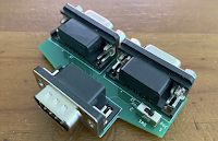
The SNES MAX Cable and the SNES MAX Socket.

What is it?

The SNES MAX is a serial interface card that allows an Apple II to communicate with SNES Controllers. It allows a slotted Apple II to read the maximum number of the SNES controller pushbuttons ie all twelve of them. The game "Attack of the PETSCII Robots", developed by David (the 8bit guy) makes use of all twelve buttons. It allows you to do cool stuff like move in one direction and fire in another (which you want to do when being chased by a pesky robot). This game only supports keyboard or SNES MAX control. Ian led the Apple II conversion effort of the PETSCII Robots game and commissioned me to make an SNES adapter, similar to what was done for the Commodore version.

The PETSCII Robots game conversion overlapped the development of the SNES MAX. It's unfortunate that the SNES MAX was not able to be completed in time for the game release (you need to run PETSCII Robots V1.1 or above for the card to work). While putting the first batch of production cards together I also converted a two player game, Mario Bros, to test and make use of SNES MAX's dual controller ability, These are the only software titles currently providing support for the card but we hope other developers come on board and help add more titles. There are a few games I have on my radar which I hope to convert some day. Other great candidates include the recent work to convert the "Game Boy" Tetris to Apple II conversion. By using an SNES controller you can closely resemble the "Game Boy" controls and capture more closely that specific controller feeling. Another great game, Roborton 2084, could use a controller upgrade. Its Apple II version resulted in a gameplay downgrade. The arcade version uses two joysticks, one for movement and one for the shooting direction. Much like the PETSCII Robots game, it could really benefit from having these independent actions. There are many other keyboard based Apple II games where the joystick control was not implemented or was cumbersome to use.

Let's be clear. The SNES MAX is not an Apple II joystick replacement. It does not operate via the Game Port. The SNES MAX uses the SNES controller protocol which reads the controllers serially just like how it's done on an SNES Console.

The SNES MAX comes in two different board layouts (the cable version and the socket version). Both boards are electrically identical. The difference lies in the connection options. The cable version of the board would suit users that predominantly would use wired SNES controllers and the socket version would suit those who plan to use a wireless solution. Either board can be used with wired or wireless controllers. The sockets allow for a cheaper solution but it means that if you are using wired controllers then the plugs will not fit through the back Apple II case slots (unless used on the early Apple II models where the back slots are open) and you will need to keep your hood open.


Things to note:
1 The wireless receivers may consume a lot of power eg the 8BitDo receivers consume about 100mA on the 5V rail. When using multiple receivers or if your system is already highly loaded you may experience power issues. Make sure you use the SNES MAX appropriately based on your power supply and existing card setup.
2. The SNES MAX Socket version results in a tight fit between slots if you have the following Apple II slot populated. Wireless receivers which are larger in physical size than the 8BitDo option may cause issues.
3. The 8BitDo receiver tends to have a very tight plug fit with the SNES sockets. I'm told this is also the case when using the 8BitDo receiver on an original SNES console.
4. The SNES MAX only works with digital signals. Even though some wireless controllers may have analog thumb sticks, the analgue signals are not used. For example the 8BitDo wireless receive converts the thumb stick 1 into the digital direction buttons while thumb stick 2 is not used.
5. Other SNES devices such as guns and multitaps are not supported. Mice may work.

The SNES MAX has been tested using an Apple IIe and a IIGS. Various different revisions of the wired controller and 8BitDo's SNES wireless receivers have been tested. Also all controllers have been tested with a lengthy extension cable.


How it works.

Early 8bit game consoles like the Atari 2600 use joysticks where each button or direction is wired directly to the game console ie parallel communications. With the advent of faster consoles and the requirement for more pushbuttons on the controller, multiplexing was selected over more signal lines (needing bigger plugs and thicker cables). This resulted in the transfer of more signal data over fewer lines ie serial communications. Some controllers try to be backwards compatible with the Atari standard like the Amiga CD32 which is half parallel and half serial and the SEGA Genesis / Mega Drive Controller which is both parallel and serial depending on a selected mode. The following generation (6 button) SEGA Genesis / Mega Drive Controller is backwards compatible and so the controller became an overly complicated solution. Alternately Nintendo's solution for its original game system, the NES, only uses serial communications which results in a very simple and elegant design. For its following generation, the SNES controller, is just an extension of this which is also nice and simple. The SNES controllers are one of the simplest of serial controllers to work with. Hence their preference over alternate controllers.


The way in which an SNES controller works is by using simple latch chips ie 2x4021, 2xW545 or 1xV520B (the NES controller only used one 4021 chip). Only three signal lines are needed between the host and the controller. A latch signal is sent from the host to the SNES controller to tell it to take a snapshot of all its pushbuttons. Then the data line is read by the host to determine if a button is on or off. Clock signals are sent from the host to the controller to tell it to send the next button press status. This results in being able to read up to sixteen digital button signals. However, the controller is physically constricted to only using the first twelve of these signals. There may be third party controllers which make use of the extra four spare buttons.

On the host side (in this case the Apple II) software needs to be written to read the SNES controller data serially. This routine takes about 500 microseconds (for two controllers ie twelve pushbuttons read from each controller) which is much quicker than the roughly 3000 microseconds it takes to read one of the Apple II analog joystick axis. You then have code on top of that which processes the data but you have to do that anyway regardless of which type of interface you have. Example software for the serial import routine can be found in the attached file at the end of this blog post.


Designing the solution.

The first decision was to select which type of interface this project was going to take. The options were

1. Remove the existing cabling out of a SNES controller and wire the twelve pushbuttons directly to a parallel input card (such as the 4Play card). The problem with this solution is that it requires the destruction of the original controller.

2. Build a buffer in between the SNES Controller and a parallel input card (such as the 4Play card). A microcontroller could be used to buffer the pushbutton signals and push these in parallel to the host. This option requires more hardware but simpler software on the Apple II side. The problem with this option is you would need two devices, the adapter and a parallel interface card. These days using a microcontroller to do the buffering is the cheapest option however back in the day this was not the case. The December 1993 copy of Popular Electronics (http://www.americanradiohistory.com/Archive-Poptronics/90s/93/PE-1993-12.pdf), starting at page 34, contains a great article on how this was achieved back in the day.

3. The serial ports on an Apple II (directly from the IIc/IIGS ports or via a serial card) use a different type of serial communication compared to that of the SNES Controller, both in electrical terms and in the terms of the protocol. A microcontroller could be build inbetween to buffer the signals and then serially send them to the host. This would involve a considerable amount of work on the hardware side and the software side.

4. Talk serially directly from the host to the SNES controller. This requires very simple hardware and relatively simple software. Hence this option was chosen for the project. There is always a trade off between designs and in this case, when comparing this solution to the parallel interface option we are sacrificing the speed of reading the data (500 microseconds instead of 40 microseconds) and in doing so make the hardware side much, much simpler. This was deemed an acceptable trade off and fits in well with the ethos of how the Apple II was designed ie optimise the hardware and let the programmer deal with what they get.

Once the type of interface was selected there were two main ways in which this could be implemented. One was to use the 16pin Game Port interface (not the 9pin Game Port because it needs to support output as well as input signals) and the other was to use the slot based interface.

I love the 16pin Game Port as a quick and easy way to do hobby experiments. However, for a durable professional solution I believe that using the Apple II slots is a much better option. I find the 16pin Game Port fiddley and difficult at times to connect in to. It's not something I would want to be plugging to and unplugging from all the time. The SNES controller adapter which uses this interface has been around for decades (https://rich12345.tripod.com/nintendo/nintendo.htm) however one must take care in its design because other circuits use this socket too (shift key mod, open and close apple buttons / joystick PB0 and PB1) meaning if diode protection is not added one can easy cause a short circuit which would not be good for the motherboard. Being such a simple build I did put it together just for laughs. It does work however it does have its issues ie CMOS - TTL theoretical incompatibility, problematic when used with certain controllers (due to region locking) and control-resetting the Apple II due to the open/close apple button tie ins.


Just a few of the official SNES Controller boards. Here are several of the SNES MAX boards used for testing.

For a durable solution, using the slot interface is definitely the way to go. I figured that being such a simple design that I could knock the project over in a day or two. Here we are a few months down the track and I'm finally getting the production boards ready for sale. It's annoying to think how much work there was for such a simple circuit. Most of the delays have come from having to wait for parts and PCBs. I have managed to get every prototype board working however they have not worked in all conditions.

I've never owned an SNES console, therefore, I've never had an SNES controller. Acquiring one was my first step in testing the first prototype. The testing went fine until I found out that Nintendo had not only region locked specific sections of their console but also region locked the controllers. It surprised me to find out how many variations there are of just the official SNES controller circuit boards. For proper testing I needed to source the other types of controllers which I did. The difference in electronics between the US/JAPAN controller and the PAL controller was not very much (pull up resistors on the latch and clock lines) but it was enough to cause issues with the first prototype. Being a tri-state design with pull-ups/pull-downs caused issues because of the region locking differences. Running the controllers via extension cables or when using two controllers at the same time exacerbated the issue. Swapping both the chips to their inverted equivalents meant keeping the same design but having an extra inverter to replace the pull-down latch circuit. This worked but the design was changed anyway to remove the need for tri-state outputs altogether and resulted in a more stable solution.

Measured resistance between 5V and the following lines
US/JAPAN, Model SHVC-005, Design 1990, Clock = 7.3k ohm, Latch = not connected.
US/JAPAN, Model SHVC-005, Design 1992, Clock = 12.8k ohm, Latch = 12.9k ohm.
PAL, Model SNSP-005, Design 1990, Clock = 1.0k ohm, Latch = 3.6k ohm.
PAL, Model SNSP-005, Design 1992, Clock = 1.1k ohm, Latch = 2.4k ohm.
8BitDo Bluetooth Wireless Receiver, Clock = 153.9k ohm, Latch = 153.2k ohm.

This design worked on my ROM1 IIGS and IIe machines but did not work on Ian's ROM3 IIGS. The wired SNES controllers would work but the wireless controllers would not. I tried to setup my IIGS as close as possible to Ian's and even tried his wireless controllers but I could not reproduce the problem. Luckily Ian had a logic analyser and hence was able to provide me with details as to what was going on. We tried a number of changes but to no avail. Having to do remote testing is never easy.

At this stage I started looking more closely at the chip design. The SNES controller is CMOS based and I had been using TTL logic to match the Apple II slots. Signals going from CMOS to TTL are not an issue but going from TTL to CMOS requires greater care. Technically the signals are not compatible and the adapter was only working for me because my TTL chips were manufactured to better tolerances than what the TTL requirement specifies. The right move was to change over to using 74HCT chips instead of the 74LS ones. With this comes extra care since CMOS chips are more prone to static damage. It was decided to include some protection circuitry. No so much to reduce electrical noise or to improve static immunity but mostly to protect the adapter from issues caused by hot plugging of the controllers.


I went back over the Apple II circuit diagrams using several different publications and I came across the signal descriptions that show that during a data output pulse video garbage can be super imposed into the first part of the pulse. I kicked myself for not knowing this. Normally this would not have been a problem since latching circuitry only looks at the pulse during the low to high Apple II clock transition and does not take the rest of the pulse into account. In our case there was no latching circuitry (the latch and clock pulses are being generated by the Apple II system clock and not by any latching chips). I find it strange that I could not reproduce these issues on any of my machines. The adapter design was changed from using the data bus to the address bus for control and this fixed the issue.

Could this design be optimised even further? Definitely. Daniel put forward some great alternative designs including a single chip version and designs where the address bus control was not required ie the clock and the data read actions could be joined together into one action. These designs do work, however, because of the tri-state design it had stability issues just like my first prototypes. Tuning could have been performed but at the expense of other factors such as a larger current draw. The issue with joining the clock and data read actions resulted in the Apple II latching the button read data on the same pulse transition as the change between buttons. It was deemed to risky to use a design that's working on the very edge of what is possible.

Just as I was putting together the first run of boards and performing unit testing, I found that a specific combination of controllers would not work together. Each controller was fine on it's own but since the clock and latch signals are shared between two controllers, a controller can affect the signals going to the other controller. The region locking issue had come back to haunt me. This time thanks to the addition of the protection circuitry. Luckily the fix did not required a PCB board change. However, I had to purchase extra controllers to perform more thorough testing and this just delayed the project even further.

I'm happy to be finally releasing the product.


Availability and distribution.

I've only just received the production boards and have put a few together to get some photos for this blog entry. I've started putting together the first run of boards as the component parts arrive. The boards will be available shortly from the USA using ReactiveMicro https://www.reactivemicro.com/product-category/lukazis-loot/ and from Australia using my "Lukazi's Loot" https://lukazisloot.blogspot.com/ website.


Future work.

I'm working with Nick to include 4Play/SNES MAX support into the AppleWin emulator. This will save me a lot of time when it comes to adding software support for these hardware projects. It will also help games such as the PETSCII Robots be more playable in the emulator.

The Bluetooth version of the 4Play card is in development (using an ESP32 chip solution so hopefully WiFi can be added in as there well). Maybe this can even be worked into a Game Port equivalent version at a later stage. The only reason that I'm mentioning this here is because I know that some people have expressed interest in getting the 4Play card at the same time as getting their SNES MAX. Not that the 4Play card will be discontinued but if you are a wireless junkie then you may wish to wait for the new card.


Thank-you.

I just want to thank all the people involved in the "Attack of the PETSCII Robots" project. Thank-you Ian for approaching me for the build and collaborating on the project. Thank-you to Kevin, Dean and Michael for your expert opinions on some of the technical details and making sure I was heading in the right direction. Thank-you to Daniel for keeping me on my toes and making sure I had double checked all the design decisions. Thank-you to the many people who helped with marketing and distribution of the product. Lastly thank-you to everyone else for your support and I wish you many years of enjoyable gaming.


Order your copy of "Attack of the PETSCII Robots" from here http://www.the8bitguy.com/26654/petscii-robots-for-apple-ii-now-available/


Update: 24th July, 2025.

Thanks to Nick's great disassembly notes, the conversion of Robotron 2084 to use the SNES MAX, was much easier than what I was expecting. The game can be found along side other goodies in the attached file below.
SNES MAX example code, schematics, etc https://docs.google.com/open?id=18MzP_IMxIK1_o9ktSFuwIrQMRhVrfkds


Update: 20th August, 2021.

The SNES MAX is now avialable from ReActiveMicro and Lukazi's Loot.

The 4Play and SNES MAX cards have been emulated in AppleWin. However, currently the configuration is limited and most things are still hard coded. Tom is helping out in getting the user interface part enhanced and getting the code integrated into the live AppleWin release.

I have tested an NES controller (NES-004) with the SNES MAX and it works well. Since the NES controller contains fewer buttons it can only be used with games like Mario Bros where fewer buttons are required. It's like having a SNES controller but where the upper protocol buttons (A, X, Front Left and Front Right) are contstantly pressed down. I'm not going to keep the cables for these in stock but I can make these up as a special order.