

Whether it's a purchase of a computer without a monitor or that last composite monitor that bites the dust or changing screens as a space saving exercise, every vintage computer enthusiast will have to deal with the display issue at some point in time. As screen technology has progressed, video adapters have been built to take up the slack from dwindling numbers of original display monitors. Trying to adapt the old computer technology to new devices and produce respectable results has been a challenge for many enthusiasts. As a monitor replacement solution I believe that it's the tablet market that holds the greatest potential going forward. Devices such as the iPad with their well proportioned screen sizes and high resolutions are ripe for image manipulation and can produce fantastic results.
The A2 Video Streamer is an alternate way to display Apple IIc or IIe video. It's made up of hardware that samples and sends video signals over high speed USB and software which runs on a computer (including tablets) and interprets those signals to produce a perfect display, at the full frame rate, in an application window. All this can be achieved with low cost, readily available parts and a page full of control code.

http://quinndunki.com/blondihacks/?p=1998

http://www.eljavo.com/en/la-apple-c-a-color/

http://www.callapple.org/documentation/technical-notes/apple-c-flat-panel-lcd-conversion/


The aim of this project was to obtain a portable display for my Apple IIc. I wanted to turn a luggable solution into a portable one. At first I was considering a hardware solution, like a composite panel however I could not find any information on anything that looked reasonable and I figured that there was a good probability that after purchasing several panels I still would not have been happy with the end result. This was way before seeing what Quinn and Javier had done with their systems. I considered other options too like the original IIc flat panels, DVD players and USB streamers. Nothing provided the results that I was after. I had an iPad sitting on the table and thought that it would make a great monitor due to its size and high resolution. I thought that it would just be an attachment that I needed but after looking into it more deeply I was shocked to find that it had no support for live video input.

http://www.exolabs.com/products.html

http://www.redmondpie.com/how-to-monitor-canon-eos-dslr-camera-from-ipad-video/
Some further investigation turned up details on WiFi streaming and USB streaming. WiFi streaming looked like quite a bit of work to develop and I suspected that the lag would be quite bad. Considering that Apple II's are now mainly used for games the lag time is critical so I turned my attention to USB streaming. There weren't many solutions in this space but I did come across two examples that were implemented so I knew it that technically it could be achieved.

http://john.ccac.rwth-aachen.de:8000/patrick/data/PALcard.pdf

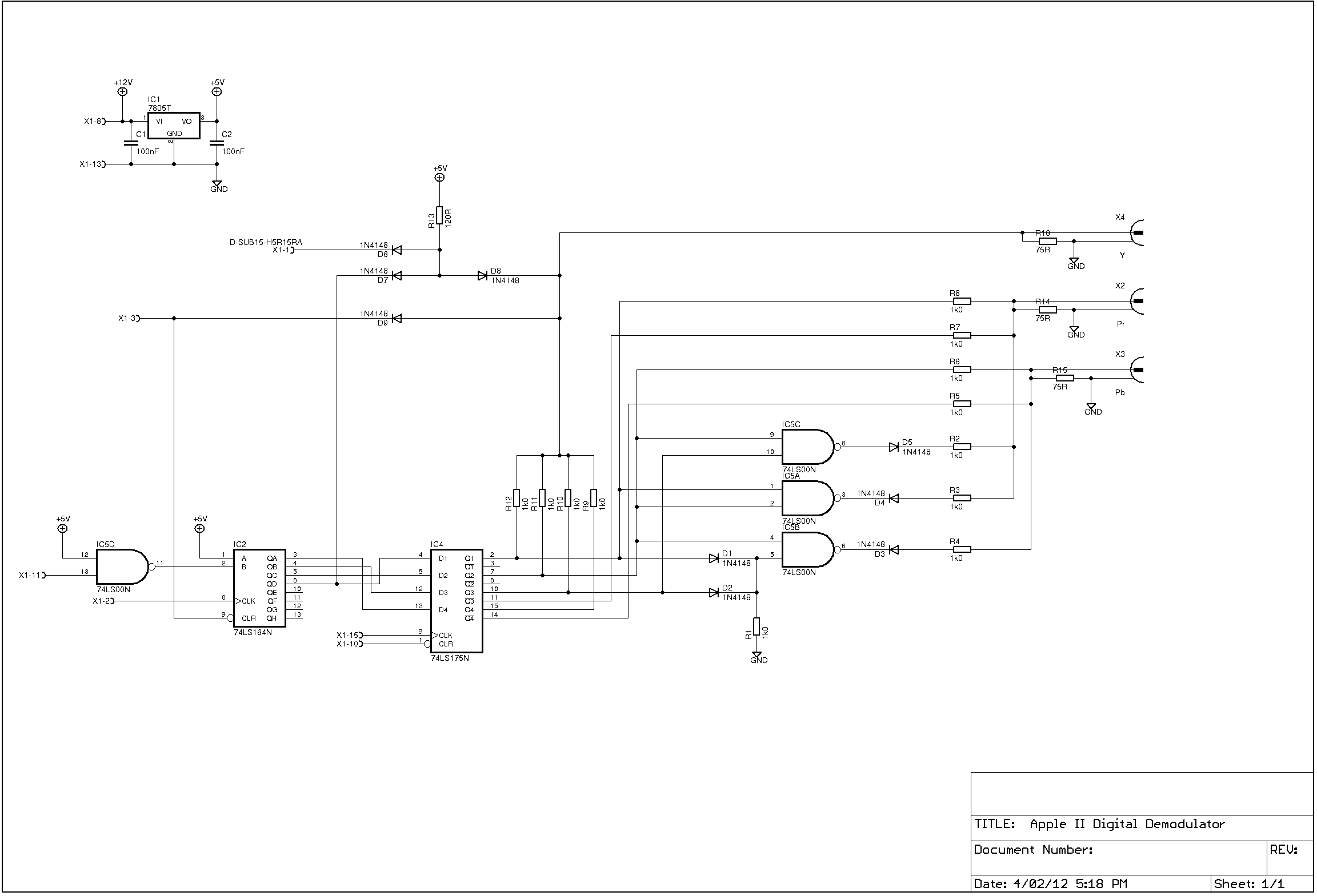
http://kaput.retroarchive.org/appleii/appleiidigital.png
I wanted to see what signals I could get out of the IIc. I remembered how simple the circuit was on the IIc video port to component converter when I was looking into getting colour on a PAL Apple IIc. Compare the two schematics above. It looks so much simpler not having to deal with composite video. I set about to understand the IIc serial video signals.


Using an oscilloscope I checked out the signals and determined that they were ok for digital sampling. I was surprised to see the 14Mhz (approx) being displayed as a saw toothed signal. The trigger point could have been an issue but at least the error would have been consistent and worst case only be out by one clock cycle. It turned out to be just fine. On went the logic analyser and I tested the video to see if I could see the "HELLO" text as displayed on the monitor.


The sync signal was the first thing I checked. It turned out that the WNDW signal was simpler to deal with and so I didn't need the SYNC signal after all. Zooming in on the waveforms gave me a bunch of pulses at the top of the sync and then a bunch at the bottom. This corresponded with the text at the top of the page and the flashing cursor at the bottom. I zoomed in again on the first group and from the pattern I could instantly recognize it as the top row of the "HELLO" text. Some of the pulses looked thicker than they should have been but that was because the logic analyser did not have a sampling frequency of 14MHz or multiple there of. This will not be an issue once the Apple II video clock is used as a timing reference.
Once I knew that it was possible to get the video signal out of the IIc I had to find a way of displaying them on a screen at the other end. I needed a package that was portable and OpenGL fitted that very nicely. I became familiar with several methods of displaying test patterns on the screen of my PC. There seems to be a lot of OpenGL setup code needed just to get a simple 560x192 picture on the screen however it will come into it's own later when scaling and rendering the image.

The next step was to get the data to the PC. Since the video out of the IIc streams at 14MHz a microcontroller was needed with high speed USB capability. The Cypress EZ-USB FX2LP microcontroller (CY7C68013A) was the best choice, not only because it is an amazing bit of kit but compared to the other high speed USB capable microcontrollers the FX2LP is well documented and there are plenty of examples from the manufacturer and of personal projects. Because it's so versatile and flexible it can be quite daunting at first. I obtained the FX2LP chip via a development board from ebay for a few bucks. It's basically just a breakout board for the microcontroller and an EEPROM added for firmware storage (I use firmware loosely here). There are several ways of making the firmware operate. The program can be burnt into the EEPROM or another method can be used that makes this device awesome. By default the microcontroller comes with a very basic USB layer that allows an application to interrogate it and find out some simple details like the manufacturer name and device model number. This facility can be used to send it the firmware from the application. Imagine what this means for the developer. This means that the firmware does not have to be set in stone. It can be downloaded to the FX2LP every time the application starts up. This also means the FX2LP can be different devices to different applications. Say a video streamer today and maybe an Apple II joystick to USB connector for your favorite PC/Mac emulator tomorrow. I still haven't decided if I'm going to use the FX2LP in this way.
The easiest way for two systems of different speeds to communicate with each other is via a FIFO (First In First Out) buffer. This is another great feature of the FX2LP. The microcontroller has a FIFO buffer in parallel with the CPU. Once the CPU finishes setting up the USB communications it is no longer needed. That's right, when sending data over USB there is no CPU processing involved. Running this way is called 'Slave FIFO' mode and this is the method I have used for this project. This mode can be used because we are not processing the data on the FX2LP. There are other modes such as 'Ports' mode which is basically bit banging the Input/Output pins using the CPU and 'GPIF - General Programmable Interface' mode which is useful when communicating to more complex devices such as FPGAs, cameras, IDE drives etc and extra logic is needed.


Firmware: Keil uVision2 Tools Software: Microsoft Visual C++ 2008
There are many configuration options when setting up USB on the FX2LP so lets just say that if all the rules are not followed to the letter then communication just does not work.
Cypress provides tools for testing USB transfers but there is a lot of ground to cover before being able to use these tools with confidence. Most of the examples from the manufacturer use the Keil uVision programming environment but since the free versions are very limiting many people have converted over to open source environments. There were examples that I wanted to use from several projects but I didn't want to create multiple environments so I stuck it out with a limited free version of Keil uVision and hacked away until I got parts working that I needed. I experienced the same issue with the application side ie the Visual C++ 2008 Express Edition. Several Cypress examples that interested me did not compile with the free version. However, I wanted to stick with this compiler because I had the OpenGL working in it. Again code was hacked to get bits working.

There are two types of high speed USB transfers that can be used BULK and ISOCHRONOUS. Currently I have only been able to get BULK transfers working. This means that the application will work so long as the USB bus does not get overloaded. Keyboards and mice are not going to add too much extra traffic but add a few drives, a printer and a web camera and the BULK method will start to throttle back the available bandwidth for our application. This results in some interesting results like screen glitches. I plan to change to ISOCHRONOUS transfers at some point to guarantee a given amount of bandwidth at all times.

The FX2LP runs on 3.3V but even though the inputs and outputs are 5V tolerant and it will work without level shifting resistors it's probably safer to include them.
Sample format.
14MHz -> Clock
WNDW Bit[0] -> Line and page sync
SEROUT Bit[1] -> Data bit
GR Bit[2] -> Determines when to process colour ie mixed graphics modes
Spare Bit[3] -> Maybe for colour - CREF?
Spare Bit[4] -> Maybe for colour - TEXT?
Spare Bit[5] -> Maybe for colour - SEBG?
Spare Bit[6] -> Maybe for colour - LDPS?
Spare Bit[7] -> Spare
When the Window, OpenGL and USB code is taken out, the remaining code is quite short. The processing part is very simple.
if (EndPt->FinishDataXfer(buffers[i], rLen, &inOvLap[i], contexts[i])) {
BytesXferred += len;
for (int iByte = 0; iByte < rLen; iByte++) {
if (!bProcessData) {
if (!(buffers[i][iByte] & 1)) {
if (iDisplayBlank > 8000) {
iDisplayY = 191;
}
else {
if (iDisplayY > 0)
iDisplayY -= 1;
}
// iDisplayX = -7; // 80 column setting.
iDisplayX = -13; // 40 column setting.
iDisplayBlank = 0;
bProcessData = TRUE;
}
else {
iDisplayBlank += 1;
}
}
if (bProcessData) {
if (iDisplayX < 560) {
if (iDisplayX >= 0) {
if (!(buffers[i][iByte] & 2)) {
color[iDisplayY][iDisplayX][0] = 255;
color[iDisplayY][iDisplayX][1] = 255;
color[iDisplayY][iDisplayX][2] = 255;
}
else {
color[iDisplayY][iDisplayX][0] = 0;
color[iDisplayY][iDisplayX][1] = 0;
color[iDisplayY][iDisplayX][2] = 0;
}
}
iDisplayX += 1;
}
else {
bProcessData = FALSE;
}
}
}
}
Here are some results.


High Resolution Graphics and Double High Resolution Graphics
Notice how the double high resolution picture is shifted to left. This also occurs with 80 column text. At first I thought this was an issue with how I was processing the data but on further inspection I found the same thing was happening on my IIc monitor. Because there is a substantial black border around the picture it's not noticeable. It's only when you apply some tape to left hand margin and change from 40 columns to 80 columns you can see the missing 80 column character.

Monochrome text can be any colour including white, green or amber.

Colour display is still a work in progress.


Normal 50% Scan Lines
Will try and match something like AppleWin output.
Presentation was given at OzKFest 2015. Thanks Andrew for putting it up on SlideShare. You can find the link here http://t.co/2UtCnuDpKg.
A quick video demonstration can be found here https://docs.google.com/open?id=0B5PVarmqxaOnVTh1YllJTmJ3R00.
Extra information :-
WNDW signal is good for synchronisation because it changes state just before the data begins but it can not be used to determine the end of line because it finishes before the data ends.
LDPS signal can be used to determine if 80 Columns/HGR or 40 Columns/GR is being used. Pulse is half the size for 80 Columns / HGR.
To determine which graphics mode is selected these signal lines are needed. Will this be needed for colour processing? I don't know yet.
Mode TEXT Mixed GR/TEXT Mixed HGR/TEXT HGR DHGR
GR = 0 5/0 5/0 5 5
TEXT = 5 0/5 0/5 0 5*
SEBG = pulse 5/5 0/0 0 0
* TEXT signal is high in DHGR mode.

Only few minor tasks still need doing. I've have them all done by next week. Only kidding.
- Complete colour video processing.
- Get ISOCHRONOUS transfers working.
- Align 80 column text / DHGR with the other modes.
- Build an adapter for the IIc video expansion port and one for the IIe expansion slot.
- Scale up the size of picture and apply rendering to reduce pixelation.
- Apply effects such as scan lines to resemble an original monitor.
- For the USB library convert to using LIBUSB instead of CyUSB for greater portability.
- Implement an application on the Mac platform.
- Implement applications on tablet platforms.
- Options editor ie type of screen to emulate, RGB colour palette editor.
Using SEROUT and accompanying signals is not difficult. I encourage you to give it a go. I’ve used this method to build a better streamer but I would like to see what others can do.
VGA cards like the Guimauve 2000 and Nishida Radio’s VGA options already process serial data. They use FPGAs to do the processing but what about using other devices such as a Raspberry Pi or a PSoC or a dedicated VGA chip?
I thought that video streaming to the iPad would take one to two days to set up. It has taken quite a bit longer and I’m only half way there.
It's still very much a work in progress however as a reference, of a working demo, here are the application and source files https://docs.google.com/file/d/0B5PVarmqxaOnUjBpUDM1bXFWSDA.
4 comments:
This sounds awesome. Keep us in the loops!
wowww
Would this work with a Raspberry Pi as the microcontroller? Or does it need this specific microcontroller that you're using?
Technically it should be possible but I don't know what operating system you would need to get the USB working as well as having real time access to the GPIO pins. You basically need to setup the Raspberry Pi as a logic analyser and then be able to sample the 14MHz signals. From having a quick look on the web for these sorts of projects it does not look like a simple task. Instead of bit banging the GPIO pins maybe SPI could be used to get the video data but then you need to get the sync signal another way.
Post a Comment